Fluid symbols power understanding graphical schematic drawings read used hydraulic equipment air tennessee middle How to read a schematic, understanding of graphical symbols used in Diagram power fluid hydraulic typical pneumatic schematics diagrams system pid figure
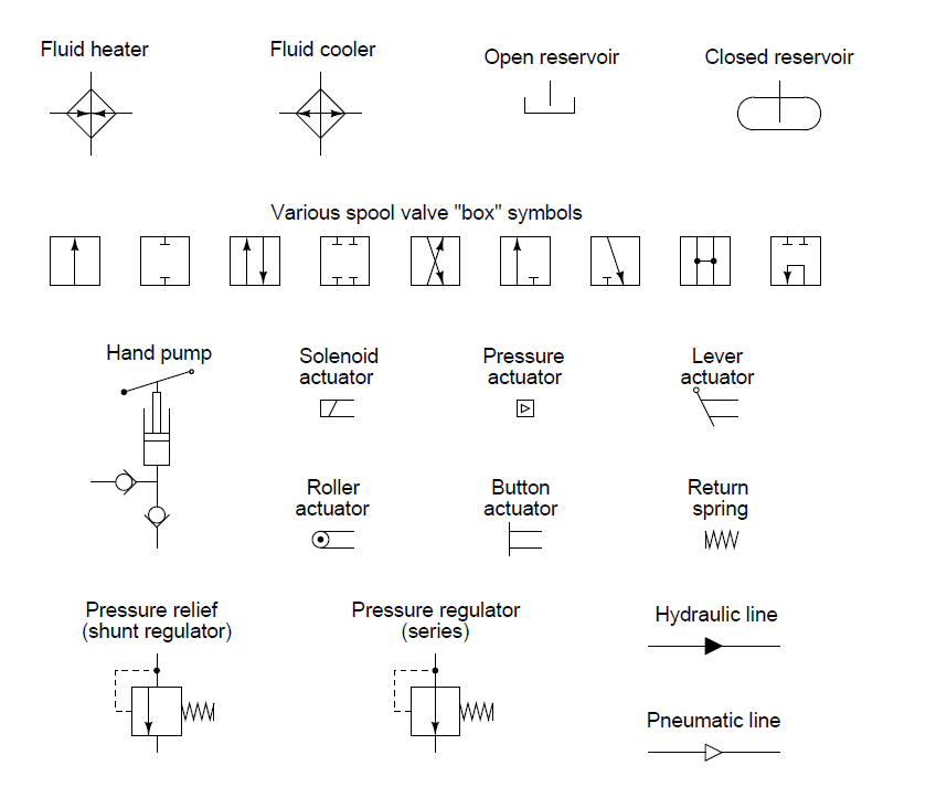
Figure 5-18.Fluid power symbols.
Fluid power schematic symbols
Fluid graphical drawings
Mechanical symbols other than aeronautical for fluid power diagramsSymbols fluid graphical power schematic hydraulic understanding drawings read used equipment air pdf tennessee middle Symbols fluid power ansi hydraulics iso pneumatics basic valves note systemsField report.
Figure 5-18.fluid power symbols.Hydraulic symbols basics fluid power basic components recognizing hydraulics circuit identify below different elements list controls very technical Hydraulic and pneumatic p&id diagrams and schematicsIso/ansi basic symbols for fluid power equipment and systems.
Fluid power symbols chart
Fluid symbols power diagrams mechanical appendix iii ii tpubFluid power symbols.pdf Symbols fluid power chart poster systemsHydraulic and pneumatic p&id diagrams and schematics.
Power diagram schematic fluid hydraulic pneumatic schematics diagrams system figure pidFluid power graphic symbols Hydraulic schematic diagram symbolsHydraulic symbols.

Fluid power symbols valve engineering figure diagrams doe
Symbols power fluid diagram figureHydraulic symbols Iso/ansi basic symbols for fluid power equipment and systemsIso/ansi basic symbols for fluid power equipment and systems.
How to read a schematic, understanding of graphical symbols used inFluid power formulas – reasontek corp Hydraulic and pneumatic p&id diagrams and schematicsSymbols fluid power interpret book educational resources.

Fluid power systems
How to interpret fluid power symbols bookEngineering symbols hydraulic schematic mechanical pneumatic diagram electrical systems common fa choose board Fluid power graphic symbolsSymbols instrumentation control fluid power flow diagram basics diagrams process systems.
Fluid power symbols chartSchematic hydraulic and pneumatic symbols Fluid power formulas symbols hydraulicFluid power formulas – reasontek corp.

Hydraulic basics: recognizing hydraulic symbols
Formulas reasontekHydraulic symbols circuit fluids diagrams symbol read pneumatic elements schematic filter strainer part common motor reading diagram drawing wiring Figure 4-5. fluid power diagram symbols.Symbols fluid power hydraulics basic pneumatics ansi iso equipment.
Reservoir symbols power fluid hydraulic pneumatic schematics diagrams pid figureControl fluid power systems system hydraulic motor pressure simple elements fluids directional uni components relief valve oil Fluid hydraulic symbols power symbol pump line below choose board flow tandem drain engineering aboveFluid power symbols diagrams aeronautical mechanical hydraulics tpub.

Mechanical symbols other than aeronautical for fluid power diagrams
Fluid graphicFluid power systems How to read a schematic, understanding of graphical symbols used inHow to read a schematic, understanding of graphical symbols used in.
Fluid power graphic symbolsFigure 26 fluid power valve symbols Industrial instrumentation and control: instrumentation and control symbolsSymbols hydraulics fluid power ansi iso basic pneumatics note charge valves.

Control fluid power systems symbols schematic diagram system components represent discrete fluids pumps
Fluid hydraulic accumulatorFluid schematic symbols hydraulic power read drawings air graphical used .
.


