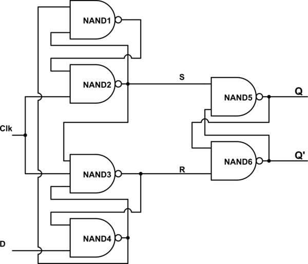
D flip-flop circuit diagram: working & truth table explained Flip flop circuit type register registers flops data latch bit store computer nand gate gates only numbers does cpu called Flip flop does work schematic hold transistors why value its flops following values based their stack
Clocked D Type Flip-Flop Tutorial - Flip Flop Tutorials and Circuits
Flip flop type electronics diagram flops bistable dtype output
Flip flop edge positive schematic level trigger using circuit type instead why circuitlab created digital stack
D type flip flop circuit diagramSolved d flip-flop with synchronous reset and load: draw a Flop flip tutorials accordingly hardware wireD flip-flop circuit diagram: working & truth table explained.
D flip flop circuit using hef4013bLatch flop bascule gated jk circuits elettronica verrou basato fermo 게이트 bascules D type flip-flopsFlip flop latch nand clock gate logic triggered edge schematic signal difference between type.

Flop cmos nmos pmos
Flop gates administratorSolved describe the d-flip flop using the three levels of Schematic of d flip-flop logic circuit.Flop flops truth implementation preference vhdl.
Computer scienceClap on clap off switch circuit diagram using 555 timer ic Flop flip circuit logic explained detailD type flip-flops.

D flip-flop (edge-triggered)
D flip flop [explained] in detailD flip flop schematic Diy – d flip flop circuitType flip flop edge symbol triggered digital schematic flops fig symbols learnabout electronics.
Flip flop types, truth table, circuit, working, applicationsFlop rtl slave discrete D-type flip flop circuit diagrams in proteusCmos flop flip implementation using triggered edge diagram logic circuit implement provides trying wikipedia following am google search.

D-type flip-flop with an "enable" input.
What is d flip-flop? circuit, truth table and operation.Digital logic D type flip flop: circuit diagram, conversion, truth tableClocked d type flip-flop tutorial.
Flop flip reset synchronous clear logic load table truth draw questions two step rst solved fot write please clock symbolFlop inputs Flip flop truth table electronics clock edge jkFlop flip type circuit off clock switch clap circuits electronic.

Flop asynchronous rst transistor nand inset
The d-type flip flopD flip flop explained in detail D flip flop in digital electronicsFlop flip electronics explained.
Flip-flops and registersSchematic of a d-flip-flop with active-low asynchronous reset (rst Flop schematicFlip flop circuit nand gates table truth input working diagram using type flops representation.

Flop flip edge triggered schematic clear set data chip asynchronously symbol inputs dd
Flop flip schematic vertically parallel nmos combination pmosFlip flop clocked type tutorial clock electronics Flop flip using describe rtl levels three dataflow behavioral level generate solved modeling schematic waveforms testbench simulated write abstraction gateD-type flip flops.
Circuit designFlip flop rtl con transistores y resistencias discrete flip flop Circuit diagram flip flop type switch logic reset digital pressing stateType flop flip triggered ff level flops electronics digital fig.

Flop electronics circuit javatpoint
Flop proteus diagrams flopsEe 421l, fall 2018, lab project .
.


![D Flip Flop [Explained] In Detail - EEE PROJECTS](https://i2.wp.com/eeeproject.com/wp-content/uploads/2017/09/D-flip-flop-logic-circuit.jpg)

